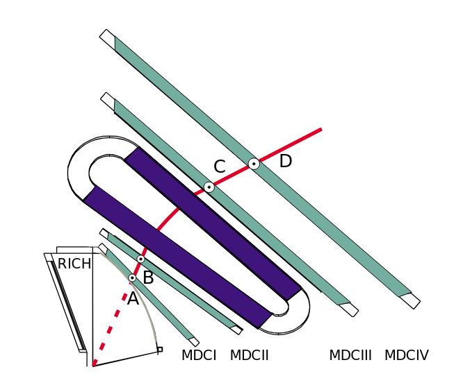
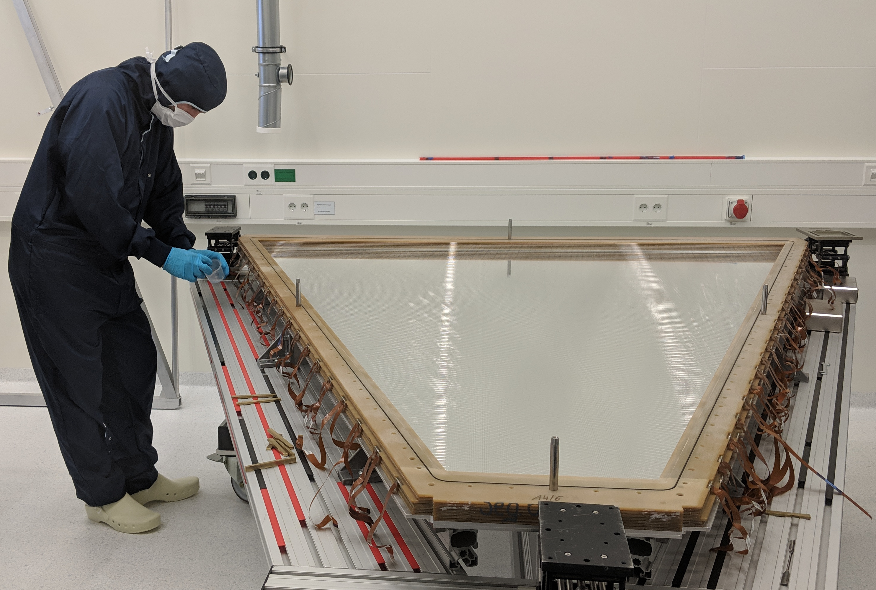
 Schematic cross-section of the HADES tracking system, with 4 drift chamber planes (MDC I .. MDC IV) |  Assembly step (frame layer 7 of 14) of MDC III, inside the clean room of GSI |
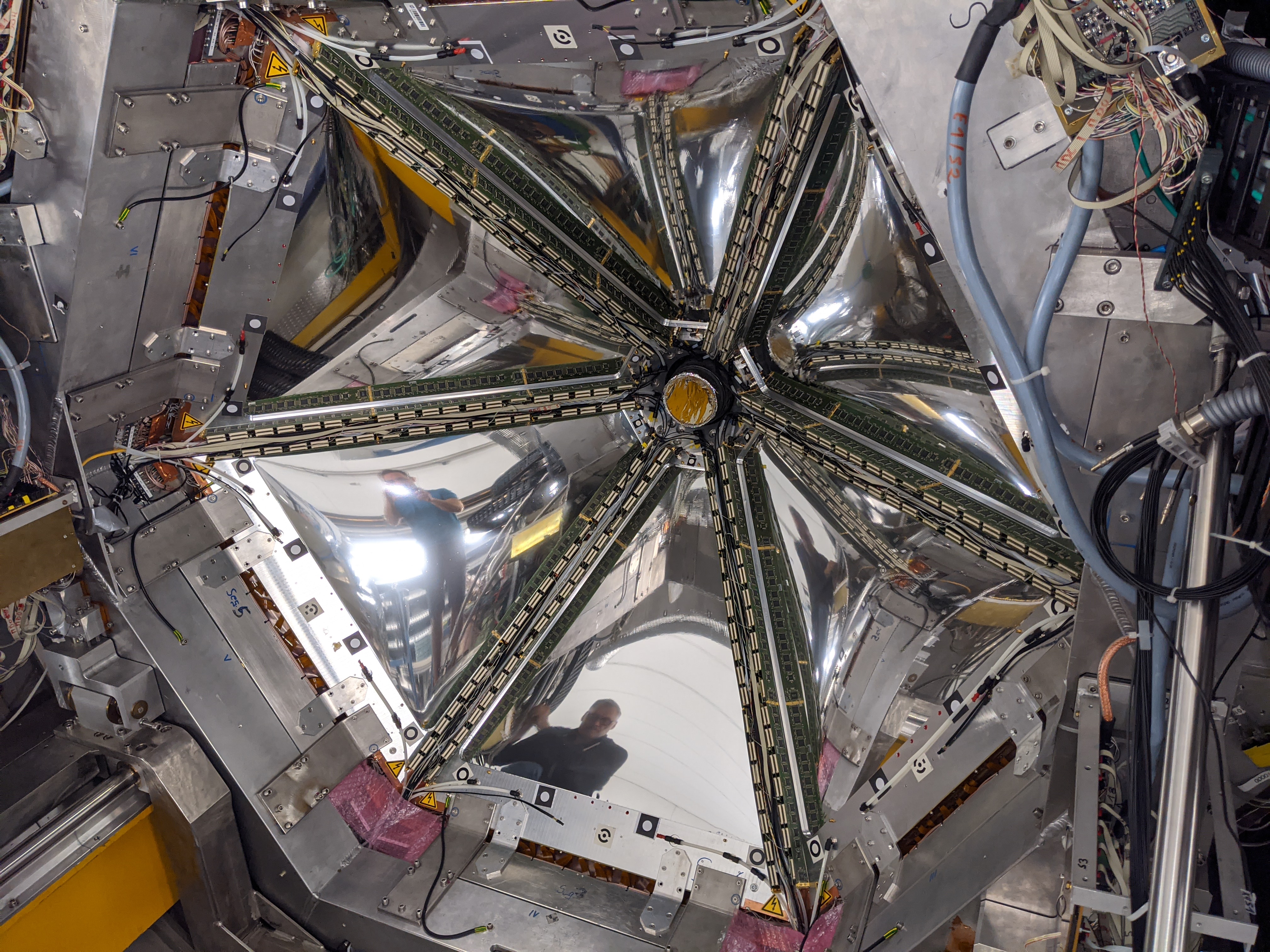
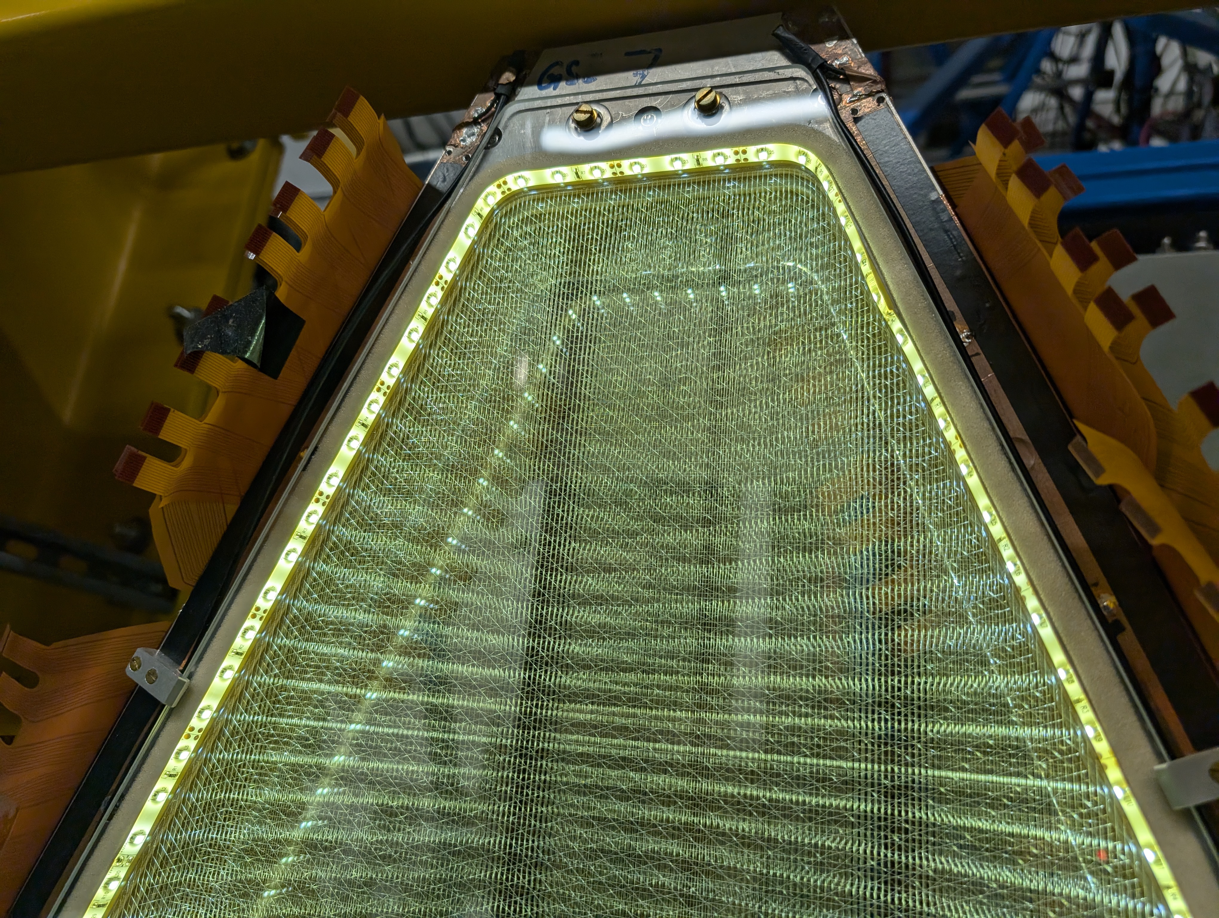
 First plane (MDC I) installed with readout electronics, behind the target downstream |  Illuminated view inside MDC I chamber, superposition of 13 wire layers |
The HADES tracking system consists of four drift chamber planes (I - IV), two before and two behind the magnetic field area of the superconducting toroid. Each of the four drift chamber planes is subdivided into six independent, trapezoidal modules defined by the geometry of the HADES superconducting magnet, covering the geometrical acceptance of HADES. Each plane is forming a frustum shape.
The inactive lateral frames of the modules are constrained by the magnet's coil boxes, which, together with the demand for minimizing the material budget inside the active volume, represents the major challenge of the module construction.
Module sizes range from 88 cm x 80 cm (plane I) to 280 cm x 230 cm (plane IV, height times larger baseline).
A chamber module is composed out of six drift cell layers. The cell sizes vary from 5x5 mm2 (plane I) to 14x10 mm2 (plane IV) from detector I to IV, to achieve a constant granularity along the particle tracks. The cells are formed by interspersed sense and field wires and cathode wire planes. The total number of drift cells is about 27.000.
The chambers were originally equipped with dedicated preamplifier/shaper/discriminator (ASD8) boards inserted into motherboards which itself contain the digitization (TDC). These daughter/motherboard components are directly mounted onto the detector frames and already offer the first stage of data reduction. In 2024, an upgrade of the front-end readout electronics has started, based on PASTTREC ASICs and FPGA chips, to address multi-hit capability and increase the readout speed.
Participating Institutions
Gesellschaft für Schwerionenforschung Darmstadt (GSI), Germany
Plane I (version 1) construction, readout electronics, chamber installation
Helmholtz-Zentrum Dresden-Rossendorf e.V. (HZDR), Germany
Plane I (version 2) III construction
Joint Institute of Nuclear Research (JINR), Russia
Plane II construction, readout electronics
Johann Wolfgang Goethe-Universität Frankfurt, Germany
Readout electronics, chamber installation
Institut de Physique Nucleaire d'Orsay (IPNOrsay), France
Plane IV construction
Related HADES Photo Gallery collections
June, 2000
Sept , 1999
June, 1999
March, 1999
March, 1999
MDC II equipped with Electronics
Oct 22, 1998
