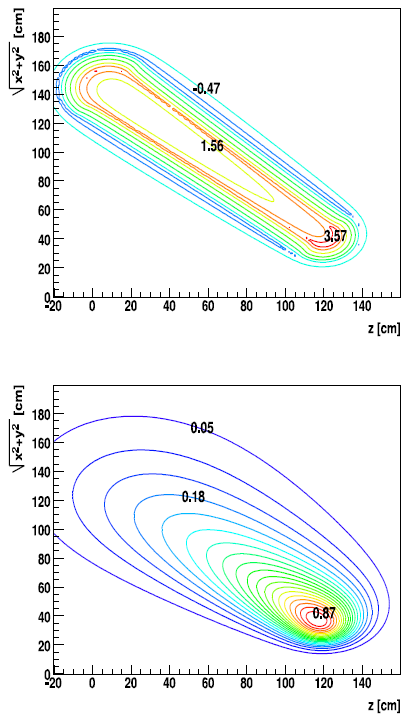
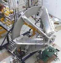
The purpose of the magnet is to provide a transverse kick to charged particles in order to obtain their momenta with sufficient resolution being of the order of σp/p = 1.5–2% for electrons. On the other hand, electron identification with the RICH detector requires a nearly field-free region around the target. Furthermore, a large momentum range of p = 0.1–2 GeV/c should be accepted simultaneously within a large solid angle (θ = 18◦–85◦, as close as possible to full azimuthal coverage). For example, at p = 1GeV/c and θ = 20◦, the deflection angle Δθk amounts to 5.7◦ for pk = 0.1 GeV/c. The toroidal field geometry provides a field-free region around the target and inside the active volume of the RICH.

The field maps exhibited in show the strong inhomogeneity of the field as a function of both polar and azimuthal angles. The maximum field is obtained at the forward arc of the coil and amounts to 3.6T at the sector edge (φ = 30◦). The field of each sector was mapped using Hall probes and a dedicated optical positioning system. After correcting for the Earth magnetic field, the measured field values agree with the ones calculated by TOSCA within better than 1%. This shows that we have a full control of the coil geometry. The agreement with the integrated field (straight line through the field region) is better than 0.2%.
The Cryo plant
The coils are surrounded by a liquid-nitrogen cooled shield at 85 K. The flow through this shield amounts to 2 g/s including all shielding components. The remaining heat load of each coil amounts to 2W. Together with the heat loadon all other components, the total load amounts to 20W excluding the current leads. The current leads are cooled with He gas, starting at 4.7K and warming up to about 270 K. The heat load depends nearly quadratically on the current with a maximum load of 80W (corresponding to 0.7 g/s) at full field. Thus, at full field, the cryo plant has to provide a cooling power of 100W, quite close to its 110W limit. All heat loads refer to an
equivalent cooling power at 4.7 K. In order to avoid gas bubbles inside the thin He pipes cooling the coils, single phase He at 4.7K and 0.29MPa is used. Above 0.23MPa (critical point), helium remains in the gas phase even at low temperatures, with density above the liquid phase at pressures below 0.23MPa. It is afterwards liquefied by expanding to 0.13MPa, providing thermal stability via heat exchangers, connecting thermally the cooling pipes with the liquid reservoir.
Magnet links of interest
General Info: delivery, commissioning, operation
- Beam-On party and celebration of the successfully commissioned magnet.
- Fast rundown resulting in a quench Dec. 1998
- Cryo turbines
- Warmup Nov, 1998
- steady state operation 1998
- Problems with the LN2 shield cooling Oct./Nov, 1998
- Magnet commissioning May-July, 1998
- Delivery of the magnet (Pictures) April, 1998
Magnet Project Reports
- Status Report: HADES Superconducting Magnet (ps)
by W. Koenig, 28. 8. 1995
Comparison of company offers, Sept. 1st 1995 in Internal HADES Documents (password protected) - Specification of the HADES Superconducting Torus System (ps.gz)
by W. Koenig, U. Kopf, D. Schüll, May 9. 1995 - HADES magnet: (ps) Part of the HADES Proposal
by the HADES Collaboration, May 1994

